
Introduction
The PosiTector 6000 hand-held, electronic instrument non-destructively measures the thickness of coatings on metals, quickly and accurately. It consists of a body (Standard or Advanced) and probe (Built-in or Separate).
Principles of Operation
F probes use the magnetic principle to measure the thickness of non-magnetic coatings on ferrous metals.
N probes use the eddy current principle to measure the thickness of non-conductive coatings on non-ferrous metals.
FN probe combine the full abilities of both the "F" and "N" probes.
PosiTector 6000 Kit Contents
Probe Only:
- Protective rubber holster with belt clip
- Certificate of Calibration traceable to NIST or PTB
- Protective Cap for Probe (some probes only)
- Quick Guide Instructions
Gage (in addition to above Probe accessories):
- Protective Lens Shield
- Wrist strap
- 3 Alkaline AAA batteries
- Nylon carrying case with shoulder strap
- USB Cable
- Precision Plastic Shim(s)
Quick Start
The PosiTector 6000 powers-up when the center navigation button is pressed. To preserve battery life, it powers-down after approximately 5 minutes of no activity. All settings are retained.
- Remove the protective plastic cap (if supplied) from probe.
- Power-up Gage by pressing the center navigation button.

- Place the probe FLAT on the surface to be measured. HOLD STEADY. When a valid measurement is calculated, the Gage BEEPS twice and the measurement is displayed.
- Lift probe AT LEAST 2 INCHES (5cm) from the surface between measurements - OR - leave probe on the surface in the same location for continuous measurements.
If memory is ON while continuous measurements are being taken, only the last value on the display (when the probe is lifted) is stored into memory.
Protective Cap
Some PosiTector 6000 models are shipped with a protective plastic cap over the probe. Remove this cap prior to use. Replace it when the instrument is not in use to protect the probe.
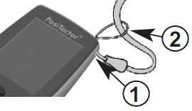
Wrist Strap
We recommend attaching and wearing the supplied wrist strap.
Plastic Lens Shield
The LCD is covered with a thin plastic film for protection against fingerprints and other marks during shipment. This film, while usually removed before using the instrument, can be left in place to protect against paint overspray. Replacements can be purchased.

Golden Rule
Measure your uncoated part first! This quick zero-check determines if a Calibration Adjustment is needed for your substrate.
Next, lay the included plastic shims onto a bare surface and measure them individually to ensure the Gage measures a known thickness within tolerance.
Certification
All probes include a Certificate of Calibration. For organizations with re-certification requirements, instruments may be returned at regular intervals for calibration. DeFelsko recommends that customers establish calibration intervals based upon their own experience and work environment. Based on our product knowledge, data and customer feedback, a one year calibration interval from either the date of calibration, date of purchase, or date of receipt is a typical starting point. Written calibration procedures are available from DeFelsko Corporation at no charge.
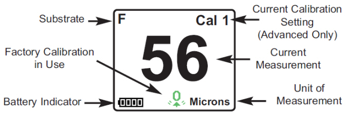
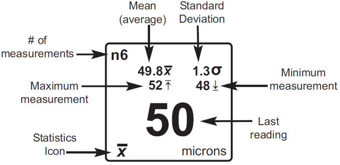
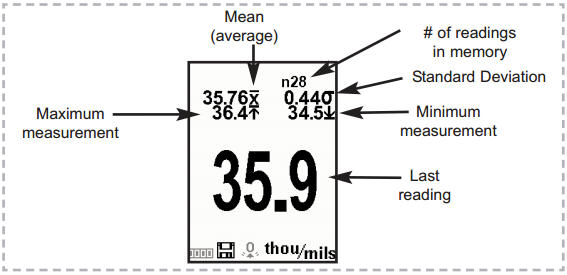
Typical Screen
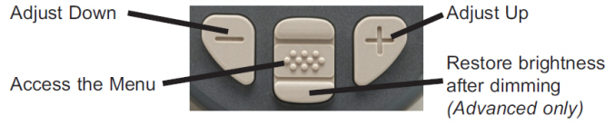
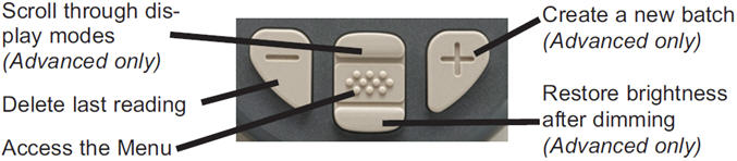
Button Functions- Normal Operation
Magnetic & Eddy Current - Theory of Operation
The PosiTector 6000 probes calculate coating thickness measurements using either the magnetic principle(F probes - ferrous models) or the eddy current principle (N probes - non-ferrous models). Combination FN probes (ferrous/non-ferrous) use both principles.
FN probes first attempt a measurement using the magnetic principle and will display a reading with the letter "F" if the coating is non-magnetic over steel. If the coating is non-conductive over metal, then the probe will automatically attempt a measurement using the eddy current principle and display a reading with the letter "N”.
Probes
The PosiTector 6000 consists of a body and a probe. A wide selection of interchangeable probes are available. Each retain their own unique calibration information. All Gage bodies accept ALL probes. More probe information is available at https://www.defelsko.com/positector-6000
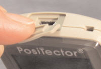
To disconnect a probe from a body, slide the plastic probe connector horizontally (in the direction of the arrow) away from the body. Reverse these steps to attach a different probe. It is not necessary to powerdown the Gage when switching probes.
When powered-up the PosiTector automatically determines what type of probe is attached and does a self-check. Coating thickness probes “sense” when they are near metal and immediately attempt a measurement followed by another every 2 seconds. They stop when removed from the vicinity of metal and power-down after 5 minutes of no activity.
This continuous measurement feature is intended to allow careful probe placement on small or odd-shaped surfaces. Ignore all readings taken before the probe is properly placed.
Two Probe Styles:
- Integral - sensor protrudes from bottom of probe connector
- Cabled - sensor is attached to the probe connector by a 1.2 meter (3 foot) cable.
(Extended cable length available.)
Available Positector 6000 Probes:
- "Regular" - These constant-pressure, stainless steel probes are hermetically sealed to be totally waterproof - ideal for underwater use.
- "Micro" - ideal for measuring small parts and hard-to-reach areas. Available in 0, 45 or 90 degree angles.
- "Thick" - ideal for thick, protective coatings.
- "Xtreme" - ideal for measuring rough and/or hot surfaces up to 250° C (500° F)
For complete details, see: https://www.defelsko.com/p6000-probe-details
Additional PosiTector Probes:
The PosiTector body accepts a wide variety of probe types including magnetic, eddy current and ultrasonic coating thickness, surface profile,environmental, Shore hardness durometer, salt contamination and ultrasonic wall thickness probes.
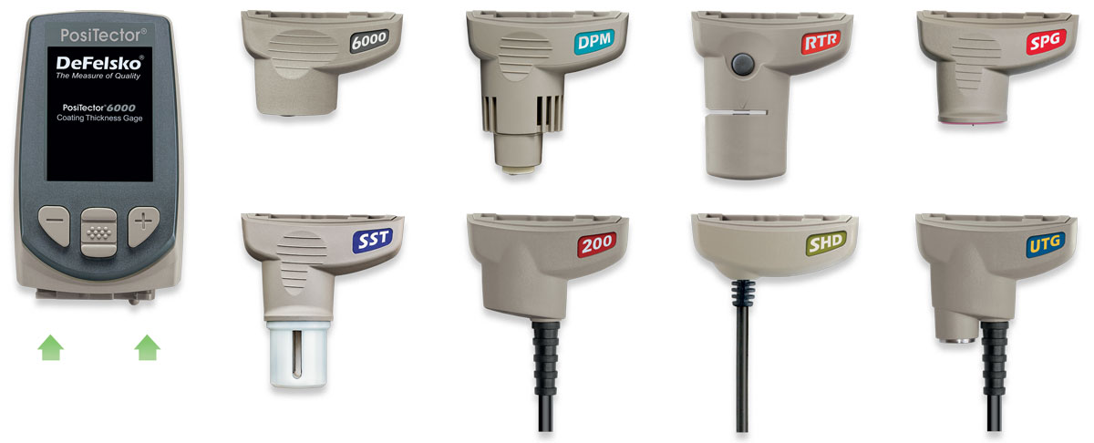
PosiTector bodies accept all PosiTector DPM, 6000, 200, SPG, RTR, SST, SHD and UTG probes
Why is Measurement Important?
Dry Film Thickness (DFT) is arguably the single most important measurement made during the application and inspection of protective coatings. Coatings are designed to perform their intended function when applied within a tight DFT range as specified by the manufacturer. Correct thickness ensures optimum product performance. Even the most basic specification will require DFT to be measured.
Many physical and appearance properties of the finished coating are directly affected by the film thickness including the color, gloss, surface profile, adhesion, flexibility, impact resistance, and hardness of the coating. The fit of pieces assembled after coating can be affected when film thickness isn’t within tolerance.
Regular film thickness measurement helps control material costs, manage application efficiency, maintain finish quality and ensure compliance with contract specifications. Paint manufacturers recommend target ranges to achieve optimum performance characteristics and clients expect these parameters to be met.
Precisely measuring finish thickness has other benefits, too. Whether to meet International Organization for Standardization (ISO), quality, or customer requirements for process control, companies need to verify coating quality to avoid wasting money reworking product.
Calibration, Verification & Adjustment
PosiTector 6000 probes non-destructively measure the thickness of coatings on metals. Three steps ensure best accuracy...
- Calibration - typically done by the manufacturer. All probes include a Certificate of Calibration
- Verification - typically done by the user on known reference standards such as plastic shims or coated thickness standards.
- Adjustment - to a known thickness
Calibration
Calibration is the high-level, controlled and documented process of measuring traceable calibration standards over the full operating range of the probe, and verifying that the results are within the stated accuracy of the probe. Calibrations are performed by the manufacturer, their authorized agent, or by an accredited calibration laboratory in a controlled environment using a documented process.
PosiTector 6000 probes are shipped with a Certificate of Calibration showing traceability to a National Metrology Institution. For organizations with re-certification requirements, probes may be returned at regular intervals for calibration. DeFelsko recommends that customers establish calibration intervals based upon their own experience and work environment. Based on DeFelsko’s product knowledge, data and customer feedback, a one year calibration interval from either the last date of calibration, date of purchase, or date of receipt is a typical starting point. Written Calibration Procedures are available online at no charge.
Verification
Verification is an accuracy check performed by the user on known reference standards. A successful verification requires the Gage to read within the combined accuracy of the probe and the reference standards.
A reference standard is a sample of known thickness(es) against which a user may verify probe accuracy. Reference standards may be plastic shims, coated thickness standards, or sample parts whose coating thickness has been determined using other means.
Verify accuracy at the beginning and the end of each work shift. During the work shift, if the Gage is dropped or suspected of giving erroneous readings, its accuracy should be re-verified. In the event of physical damage, wear, high usage, or after an established calibration interval, the probe should be returned to the manufacturer for repair or calibration.
Adjustment
Adjustment, or Cal Adjustment, is the physical act of aligning the probe’s thickness readings to match those of a known thickness sample (removal of bias) in order to improve the accuracy of the probe on a specific surface or in a specific portion of its measurement range. 1-point or 2-point Cal adjustments are possible.
Probes are factory calibrated and perform an automatic self-check each time a measurement is taken. For many applications no further adjustment is necessary after a Reset. Just check ZERO on the uncoated substrate, then measure. However, sometimes probe readings can be influenced by changes in substrate shape, composition, and surface roughness or by measuring in a different location on the part. That is why Cal adjustments are made possible. The ![]() symbol disappears whenever a Cal adjustment is made.
symbol disappears whenever a Cal adjustment is made.
Where a Cal adjustment method has not been specified, use a 1-point method first. If measuring the included shims on your uncoated surface reveals inaccuracies, use the 2-point method. Factory Cal settings can be restored at any time by performing a Reset, creating a NEW Cal setting (See Cal Memory), or by DELETING the adjustments made to the Cal 1 calibration setting. The ![]() symbol appears on the display whenever factory Cal settings are in use.
symbol appears on the display whenever factory Cal settings are in use.
With “FN” probes, calibration adjustments are made only to the “F” or “N” mode (stored independently under a particular Cal), whichever was measured last.
Menu Operation
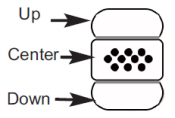
Instrument functions are menu controlled. To access the Menu, power-up the instrument, then press the center navigation button ![]() .
.
Below is a sample menu for a PosiTector 6000 Advanced Mode:
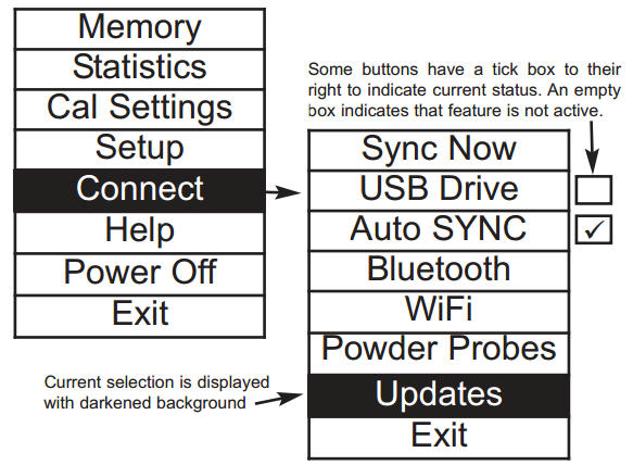
To navigate, use the Up and Down buttons to scroll vertically and ![]() to SELECT.
to SELECT.
To navigate, use the Up and Down buttons to scroll and ![]() to SELECT.
to SELECT.
Select Exit to exit from any menu.
Cal Settings Menu
1-point Calibration Adjustment
Also known as an offset or correction value, there are 4 ways to perform this adjustment:
(i) Simple Zero Calibration Adjustment
Measure your uncoated part. If the Gage does not read "0" within the tolerance of the probe being used, lift the probe from the surface and adjust the display down (-) or up (+) until it reads "0". Measure and adjust until the average of a series of readings on the uncoated surface is within tolerance of "0".
(ii) Average Zero Calibration Adjustment
To establish "0" on a rough or curved surface a preferred method to (i) is to take several readings on the uncoated part and average the result.
(a) Select from the Cal Settings menu.
(b) Press (+) to select the number of readings to be used to obtain an average, typically 3 to 10 readings. The greater the variation between readings, the more readings should be taken to obtain an average.
(c) Repeatedly measure the uncoated part. The Gage will wait 2 seconds after placing the probe on the surface to allow the user to correctly position the probe on the surface. After the last measurement the Gage will calculate a Zero which represents the average of all the Zero readings taken.
(iii) Simple Adjustment to a Known Thickness
It is sometimes desirable to adjust the Gage to a known thickness, such as a shim, rather than adjusting it to zero.
Measure the object. If the expected reading is not obtained (within tolerance), lift the probe from the surface and adjust the displayed reading down (-) or up (+) to the expected thickness. Hold the button down to increase the rate of adjustment.
(iv) Average Adjustment to a Known Thickness
On rough or curved surfaces a preferred method to (iii) is to take several readings on the known thickness and average the result.
(a) Select from the Cal Settings menu.
(b) Press (+) to select the number of readings to be used to obtain an average, typically 3 to 10 readings. The greater the variation between readings, the more readings should be taken to obtain an average.
(c) Repeatedly measure the known thickness reference. The Gage will wait 2 seconds between readings to allow the user to correctly position the probe on the surface. After the last measurement the Gage will calculate and display the reading which represents the average of all the measurements taken. If the expected reading is not obtained (within tolerance) life the probe from the surface and adjust the reading down (-) or up (+) to the expected thickness and press ![]() .
.
2-point Calibration Adjustment
Preferred method for very unusual substrate materials, shapes or conditions. Provides greater accuracy within a limited, defined range.
1. Select from the Cal Settings menu.
2. Press (+) to select the number of readings to be used to obtain an average on the thinner item, typically 3 to 10 readings. The greater the variation between readings, the more readings should be taken to obtain an average.
3. Repeatedly measure the thinner item. The Gage will wait for 2 seconds on the surface to allow the user to correctly position the probe on the surface. After the last measurement the Gage will calculate and display a thickness value which represents the average of all the readings taken using the factory calibration settings.
4. Lift the probe fomr the surface and adjust the displayed reading down (-) or up (+) to the known thickness value of the thin item. Press to accept this value.
5. Repeat steps 2 - 4 for the thicker item.
When selected, the ![]() icon will appear and all calibration settings are "locked" to prevent further user adjustments. Uncheck to make further adjustments.
icon will appear and all calibration settings are "locked" to prevent further user adjustments. Uncheck to make further adjustments.
(FN ferrous/non-ferrous combination probes only)
Select N Lock (Non-Ferrous Lock) when operating regularly on non-ferrous substrates. The ![]() icon will appear and the probe will only use the eddy current principle to shorten measurement time and extend battery life.
icon will appear and the probe will only use the eddy current principle to shorten measurement time and extend battery life.
N Lock is useful when measuring coatings on plated steel. Normally the probe measures both the coating + plating over the steel using the magnetic principle. N Lock makes the Gage measure the coating over the plating only.
Select N Lock to measure over slightly magnetic substrates; i.e. clear-coat on gold over nickel-plated brass. Although the probe's magnet is used for the magnetic principle, it is also used in N Lock to magnetically saturate a slightly magnetic substrate and allow the eddy current principle to operate unhindered.
CAUTION: With N Lock engaged it is possible to obtain a reading when measuring non-conductive coatings on steel. This is not recommended.
Calibration Memory
(Advanced models only)
It is often convenient to store a particular calibration adjustment before making another. Then, if you return to that part, the corresponding calibration setting can be restored.
A “setting” is any calibration adjustment. The PosiTector 6000 always displays the current calibration setting (ex. Cal 3) in the upper right corner of the display.
The setting called Cal 1 has unique features. It can be adjusted but never deleted, and is always made active with factory settings after a Reset.
Creates a new calibration setting using the next available number (Maximum of 10). By default, these new Cal settings are initially created with the Gage’s factory settings. This is indicated with the ![]() icon which appears at the bottom of the display. A warning message will prevent the creation of a new Cal Memory if a batch
icon which appears at the bottom of the display. A warning message will prevent the creation of a new Cal Memory if a batch
is open and has readings. Delete the batch first.
Loads an existing setting. Use the Up or Down buttons to scroll until the desired setting appears, then press![]() . A warning message will prevent the opening of a stored Cal setting if a batch is open and has readings. Create a new batch first or open a batch containing no readings.
. A warning message will prevent the opening of a stored Cal setting if a batch is open and has readings. Create a new batch first or open a batch containing no readings.
Removes a setting completely from the list. That Cal number can be reused later with the New command. A setting cannot be deleted if readings have been stored into a batch using that calibration setting. Delete all readings in that batch first. Although Cal 1 cannot be deleted, the Delete function will return it to factory settings.
View stored Calibration Settings.
Setup Menu
Reset (menu reset) restores factory settings and returns the Gage to a known condition. The following occurs:
- All batches, stored measurements, images, and batch names are erased.
- The
 icon will appear on the display.
 - Menu settings are returned to the following:
| Memory = OFF | Cal Lock = OFF |
| High Res = OFF | Bluetooth = OFF |
| Statistics Mode = OFF | Display = None |
| Hi Lo Alarm = OFF | N Lock = OFF |
| Scan Mode = OFF |
Perform a more thorough Hard Reset as follows:
- Power down te Gage and wait 5 seconds.
- Simultaneously press and hold the (+) and center buttons until the Reset symbol appears.
This returns the Gage to a known, "out-of-box" condition and performs the same function as a menu Reset with the addition of:
- All calibration adjustments and Cal Memory are cleared and returned to the Gage's factory calibration settings.
- Bluetooth Pairing is cleared.
- Menu settings are returned to the following:
| Units = microns | Language = English |
| Flip Display = Normal | Battery Type = Alkaline |
| Auto Sync = OFF | Backlight = Normal |
| Fast Mode = OFF | Bluetooth Streaming = OFF |
| USB Drive = ON |
NOTES:
- Keep the Gage away from metal during a Reset
- Date, Time and WiFi are not affected by either Reset
Selects display brightness (Sun, Normal or Night). All settings will dim slightly after a period of no activity to conserve battery life. Press the Down button to brighten the display.
Increases the displayed Gage resolution as follows:
| Resolution | Range |
| 0.01 mil | 0.00 - 99.00 mils |
| 0.1 mil | 100.0 - 999.9 mils |
| 0.1 μm | 0.0 - 999.9 μm |
| 1.0 μm | over 1000 μm |
NOTE: Gage accuracy is not affected.
Increases measurement speed for most probes. Useful for quick inspection or when measuring large areas with thick coatings where proper probe positioning is not critical. Swift up/down probe movement is required. Reduced accuracy may be noted.
(Advanced models only)
By default, the PosiTector 6000 takes approximately 1 reading per second. Scan mode allows the user to take multiple readings in rapid succession (3 readings per second) without lifting the probe. Choose from 3 Scan modes:
- Normal - continuously measures when placed on the surface.
- Statistics - displays real-time scan statistics when placed on the surface. Average, max., min., and standard deviation are displayed.
- Limited # Avg. - continuously measures until user-specified number of readings is reached, then displays the average for the scan.
When Memory is on, Scan measurement data is recorded. However, in Statistics and Limited # Avg. Scan modes, only the statistics and/or average is saved, not individual readings. Note that performing a scan may reduce the life of the probe and is recommended for smooth surfaces only. For additional information concerning Scan mode, visit https://defelsko.com/scan
Displays the model number & serial number, probe type & serial number, PosiSoft.net registration key, the amount of remaining memory for storage of readings, date and time, and software packages.
For security purposes, the registration key is required to add the Gage to your free PosiSoft.net account.
This option causes the display to rotate 180°. Ideal for right-sideup viewing when the sensors are pointed away from the user.
All measurements are date and time stamped (24 hour format) when stored into memory. It is therefore important to keep both the date and time current using this menu option. Use the Up and Down buttons to scroll, and the (-) and (+) buttons to adjust a value. The Gage’s data and time can also be viewed in Gage Info.
Selects the type of batteries used in the Gage from a choice of “Alkaline”, “Lithium” or “NiMH” (Nickel-metal hydride rechargeable). If NiMH is selected, the Gage will trickle charge the batteries while connected via USB to a PC or optional AC charger (Gage must be powered ON). The battery state indicator icon is calibrated for the selected battery type. No damage will occur if the wrong battery type is selected.
DeFelsko recommends eneloop (NiMH) rechargeable batteries.
Converts the display from inch to metric or vice versa. Stored measurements in memory are not converted. Switching units will turn off Statistics, HiLo Alarm and closes memory.
Converts displayed and printed words to the selected language.
Statistics Menu
When selected, a ![]() icon and statistical summary will appear on the display.
icon and statistical summary will appear on the display.
Remove the last measurement by pressing the (-) button. Press (+) to clear statistics.
Allows the Gage to visibly and audibly alert the user when measurements exceed user-specified limits.
When HiLo Alarm is selected, the current Lo setting is displayed. Adjust down (-) or up (+). Alternatively, measure a coating with a thickness close to the required value and make final adjustments with the buttons. Select NEXT to accept this value. The current Hi setting is now displayed. Follow the same procedure to adjust the Hi setting.
The ![]() icon will appear on the display.
icon will appear on the display.
Measurements will be compared to your defined HiLo limits. The Gage beeps if results are within those limits. A single low tone will sound if the reading is below the Lo limit, and a high tone if it is above the Hi limit. Press (+) to clear HiLo readings.
Clears all on-screen Statistics and HiLo tabulations.
Memory Management
The PosiTector 6000 has internal memory storage for recording measurement data. Stored measurements can be reviewed on-screen or accessed via computers, tablets and smart phones. Measurements are date and time-stamped.
The  symbol appears and basic statistics are displayed when the Gage is set to store measurement data.
Button functions with Memory ON:
Standard models store up to 250 readings in one batch. The Memory Menu includes the following options...
- On: turns memory on and begins recording
- Off: stops recording (stored readings remain in memory)
- Clear: removes all readings from memory
- View: lists group statistics and all stored readings on the display. It will begin by showing statistics based on all readings in memory. Use the Up and Down buttons to scroll through all readings. Press to exit.
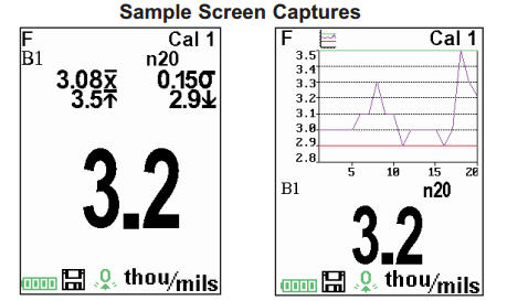
Standard model display with Memory ON shows measurement statistics.
Advanced models store 100,000 readings in up to 1,000 batches. The Memory Menu include the following options...
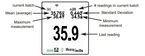
Closes any currently opened batch and creates a new batch name using the lowest available number. For example, if only Batch 1 and Batch 3 exist, then Batch 2 would be created and made the current batch. Each measurement will be displayed and stored into this new batch. On screen statistics are immediately updated with each measurement. New batch names are date stamped at the time they are created.
Shortcut: When a batch is open, press (+) to create a new batch
NOTES:
- Remove the last reading from the current open batch by pressing (-).
- Calibration adjustments cannot be made if readings are stored in memory.
(appears only if a batch is currently open)
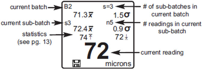
Creates a new sub-batch within the currently opened batch.
Shortcut: When a sub-batch is open, create a new sub-batch by pressing (+).
In the following example, B2s2 is a sub-batch of Batch 2. Sub-batching allows the user to group related batches so that statistics can be accumulated for them. Batch 2 contains the statistics for B2s1 and B2s2.
Helps determine if film thickness over a large area conforms to user specified min/max levels. See www.defelsko.com/pa2.
Determines if a coating system complies with the IMO performance standard for protective coatings. See www.defelsko.com/9010.
Selects a previously created batch or sub-batch name to open and make current. If it contains measurements, on-screen statistics will immediately reflect values calculated from this batch. The calibration setting (i.e. Cal 2) associated with this batch is also opened.
NOTE: A solid triangle ![]() is displayed to the right of the batch name when sub-batches are present. Press
is displayed to the right of the batch name when sub-batches are present. Press ![]() to view subbatches. This also applies to the Delete, View and Print options.
to view subbatches. This also applies to the Delete, View and Print options.
Stops the recording process, closes the current batch, and removes batch information from the display.
Removes a batch or sub-batch completely from memory. The name is deleted and all measurements are erased. Sub-batches can be deleted individually. To delete all related sub-batches, simply delete the top-level batch.
Scroll using the Up or Down buttons through information, statistical summary, and a list of each reading in the currently opened batch. Press ![]() to exit.
to exit.
(Advanced models only)
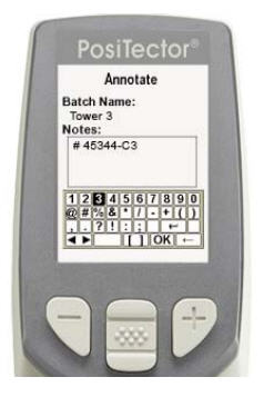
Create meaningful batch names and enter notes directly on the Gage using a familiar onscreen QWERTY keyboard.
Use the Gage's navigation and (-)(+) buttons to enter annotations.
Annotations can be synchronized with PosiSoft.net and the PosiTector App and are included in PosiSoft USB Drive reports.
Sends a statistical summary and individual measurements to the optional Bluetooth wireless printer.
NOTE: To cancel printing, press and hold the (-) and (+) buttons simultaneously.
(appears only if a batch is currently open)
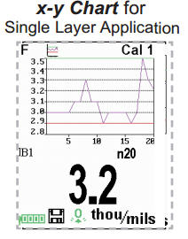
The following chart user selectable display options are available:
![]() Chart: A real-time chart of batch readings
Chart: A real-time chart of batch readings
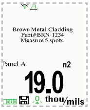
 Notes: Instructions, descriptions or notes (see Annotate)
None: Default screen shows statistics
Shortcut: When a batch is open, press Up to scroll through the above display options.
NOTES:
- PosiSoft.net and the PosiTector App are used to insert an Image and Notes into a batch.
- Remove the last reading from the current open batch by pressing (-).
- Calibration adjustments cannot be made if any measurements were taken with that setting and stored into a batch.
- If memory is ON while continuous measurements are being taken, only the last value on the display (when the probe is lifted) is stored into memory. Scan Mode stores ALL measurements into memory.
- Each batch can contain a maximum of 10,000 readings.
(Advanced models only)
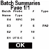
Displays a summary of all stored batches including the name, probe type, number of readings and type.
In the following example, Batch 3 (B3) indicates an “F” 6000 coating thickness probe was used to record a total of “6” readings in “PA2” mode.
Press both (-)(+) buttons at any time to capture and save an image copy of the current display. The last 10 screen captures are stored in memory and can be accessed when connected to a computer (see PosiSoft USB Drive).
Accessing Stored Measurements Data
DeFelsko offers the following free solutions for viewing, analyzing and reporting data:
PosiSoft USB Drive
Connect the Gage to a PC/Mac using the supplied USB cable. View and print readings and graphs using universal PC/Mac web browsers or file explorers. No software or internet connection required. USB Drive must be selected in the Gage’s “Connect > USB” menu.
PosiSoft Desktop
Powerful desktop software (PC/Mac) for downloading, viewing, printing and storing measurement data. Includes a customizable, templated PDF Report Generator. No internet connection required.
PosiSoft.net
Web-based application offering secure, centralized storage of measurement data. Access your data from any web-connected device.
PosiTector App
(Advanced models only, s/n 784000+)
App for compatible iOS and Android smart devices. Permits users to create, save and share professional PDF reports. Add images and notes using the smart device’s camera and keyboard.
Learn more at https://www.defelsko.com/posisoft/software
Connect Menu

(Advanced models only)
Allows connection to your local wireless network or mobile hot spot. Ideal for using your network's internet connection for synchronizing stored measurements with PosiSoft.net. See www.defelsko.com/wifi
Turns WiFi functionality ON. When selected, the ![]() icon will appear on the display. To deactivate WiFi, uncheck the Enable box.
icon will appear on the display. To deactivate WiFi, uncheck the Enable box.
Connect your smart device/computer to a PosiTector Advanced body wirelessly without the need for a separate network. Wirelessly import readings into PosiSoft Desktop v4.0 Software whenever a WiFi network is not available or out-of-range.
To enable, select Access Point from the Connect > WiFi menu. The Access Point icon ![]() will display in the upper left of the PosiTector display.
will display in the upper left of the PosiTector display.
Securing your Access Point -
To ensure the PosiTector is only accessible to authorized devices, it is important that you enter a passphrase (password) for the Access Point. The default Passphrase is password.
In the Connect > WiFi > Setup menu, select AP Passphrase.
Press ![]() button to display on-screen keyboard. Enter a Passphrase for the Access Point. The Passphrase will be required for all devices connecting to the PosiTector's Access Point.
button to display on-screen keyboard. Enter a Passphrase for the Access Point. The Passphrase will be required for all devices connecting to the PosiTector's Access Point.
The PosiTector is now visible to all WiFi enabled devices. Simply connect your devices WiFi to the new PosiTector Access Point. All PosiTectors are uniquely identified by their respective gage body serial numbers.
AP Channel - Default Channel: 6
For most users the default channel will not have to be altered. If you are experiencing poor connection or are unable to connect, try another channel.
In the Connect > WiFi > Setup menu, select AP Channel
Press the UP center navigation button to highlight the channel. Use the (-) or (+) buttons to change the channel. Press the DOWN navigation button and select OK. Press the ![]() button.
button.
Networks: With WiFi Enabled the Gage will allow the user to add a new network and will automatically check for available local networks. Available networks detected by the Gage are listed on the screen along with any networks that the Gage has previously been connected to that are not currently within connection range.
Information: Gage displays information about the local WiFi network connection including...
- SSID: the network's name
- State: displays if the Gage is connected to the network or not
- IP Address: the network's IP Address
Setup: Allows user to setup a WiFi connection - IP Settings: enter the IP information as follows...
IP Type (DHCP or Statis), IP Address,
Gateway, Netmask, DNS1, DNS2 - Server Enable: enables a connection between the network and the Gage
- Gage Name: enter a name for the Gage (up to 14 characters)
AP Channel: The access point channel corresponding to a frequency range. (Default Channel: 6)
AP Passphrase: A series of characters, numbers or symbols used to log on to a WiFi network. (Default Passphrase: password) - WiFi Reset: erases all WiFi settings
When USB Drive is checked ![]() , the PosiTector gage uses a USB mass storage device class which provides users with a simple interface to retrieve stored data in a manner similar to USB flash drives, digital cameras and digital audio players.
, the PosiTector gage uses a USB mass storage device class which provides users with a simple interface to retrieve stored data in a manner similar to USB flash drives, digital cameras and digital audio players.
USB Drive is also required to import stored measurements into PosiSoft Desktop software (pg.24). Once connected, any computer can view measurements stored in memory by navigating a virtual drive labeled "PosiTector” using the included USB cable.
A formatted HTML report is viewed by selecting the "index.html" or “START_HERE.html” file found in the root directory. Optionally, text ".txt" files located in each batch folder provide access to measurement values. Stored datasets and graphs can be viewed or copied using universal PC/Mac web browsers or file explorers.
When your PosiTector is first connected to your Windows PC via a USB cable, an enumeration process is started that installs device drivers without re-booting your computer. You may see several pop-up windows in the taskbar at the bottom right of your screen. Wait for the entire process to be completed before proceeding.
Serial Streaming via USB (Advanced models only, serial numbers 784000 and greater)
Advanced gage bodies have the ability to serial stream live readings from the USB port.
The following document links will help operators use this feature:
- PosiTector Advanced USB Serial Streaming Instructions -- https://dl.defelsko.com/resources/PosiTectorAdvanced-USBserial.pdf
- Required driver (referenced in above document) -- https://dl.defelsko.com/software/gserial.zip
Retrieving stored screen captures:
The last 10 screen captures stored in memory can be accessed by navigating to the "screen capture" directory within the "PosiTector" virtual drive.
NOTE: When connected, power is supplied through the USB cable. The batteries are not sed and the body will not automatically power down. If rechargeable (NiMH) batteries are installed, the instrument will trickle charge the batteries.
The below WiFi, USB and Bluetooth menus contain a Sync .net Now option. When selected, the Gage immediately synchronizes stored measurement data via its respective communication method (internet connection required).
Alternatively, select Auto Sync .net from within the USB connect menu to automatically synchronize upon connection to a PC. Additional measurements added to memory while connected are synchronized only when the USB cable is disconnected and reconnected, or when the Sync .net Now option is selected.
WiFi connected gages automatically attempt synchronization upon power-up.
NOTE: PosiSoft Desktop is required when using USB or Bluetooth connections to synchronize measurements with PosiSoft.net.
(Advanced models only, serial numbers 784000 and greater)
When Enabled ![]() , allows communication with a smart device running the PosiTector App via auto-pairing Bluetooth Smart (BLE) wireless technology.
, allows communication with a smart device running the PosiTector App via auto-pairing Bluetooth Smart (BLE) wireless technology.
Select ![]() batches to flag them for synchronization to the PosiTector App. New batches created while Bluetooth Smart is enabled are automatically selected.
batches to flag them for synchronization to the PosiTector App. New batches created while Bluetooth Smart is enabled are automatically selected.
With Bluetooth Smart enabled, select Sync Batches to transfer selected batches to the PosiTector App. This is useful when switching between smart devices, as only readings and batches that have yet to be synchronized with any smart device are synchronized automatically.
NOTE: If Bluetooth Smart is disabled, data from batches selected in the Sync Batches menu are held in a queue until communication with the PosiTector App is re-established.
Transfers selected ![]() batches to the PosiTector App (useful when switching between devices).
batches to the PosiTector App (useful when switching between devices).
The Send Batches option is visible in the menu when the Gage is connected to a smart device running the PosiTector App.
(Advanced models only)
Allows individual readings to be sent to a computer, printer or compatible device as they are taken using Bluetooth wireless technology. See www.defelsko.com/bluetooth
The instrument and receiving device must be paired before stored or streamed datasets can be transmitted. For pairing instructions, see www.defelsko.com/bluetooth
Lists information about your current Bluetooth connection, including the currently paired device and MAC address.
When checked, the instrument will stream datasets to the paired Bluetooth Device as they are taken. Datasets can be streamed as they are taken to the optional Bluetooth printer or third-party computer software.
Displays menu options that enable the PosiTector Advanced body to communicate with wireless PosiTector PC probes. See www.defelsko.com/pc
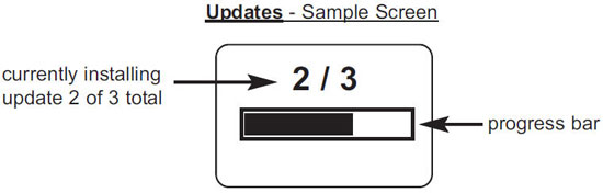
Determines if a software update is available for your Gage. If an update is available, a prompt will appear allowing the user to choose to perform the update at this time or not.
To perform an update the Gage must be connected to an internet connected computer with PosiSoft Desktop, or WiFi network.
NOTE: Ensure that stored measurements are backed up to a PC or PosiSoft.net.
![]() DO NOT unplug the Gage during the update operation.
DO NOT unplug the Gage during the update operation.
Temperature
Operating Range: +32° to +120°F (0 to +50°C)
The PosiTector 6000 compensates automatically for temperature. Allow a few minutes for the probe to reach ambient temperature before measuring.
Discard the first measurement taken in a notably different temperature condition. When measuring surfaces much hotter or colder than ambient, lift the probe at least 6 inches (15cm) and allow at least 1 second off the surface between measurements.
Power Supply / Battery Indicator
Power Source: 3 AAA alkaline, Lithium or optional Nickel-metal hydride (NiMH) rechargeable batteries. For best battery indicator results, ensure the appropriate Battery Type is selected in the Setup > Battery Type menu.
The battery indicator ![]() displays a full bar with fresh alkaline or fully charged batteries installed. As the batteries weaken, the bar will be reduced. When the battery symbol is low
displays a full bar with fresh alkaline or fully charged batteries installed. As the batteries weaken, the bar will be reduced. When the battery symbol is low ![]() the Gage can still be used, but the batteries should be changed or recharged at the earliest opportunity. The Gage will turn off automatically when batteries are very low, preceeded by a Low Battery Warning on the display.
the Gage can still be used, but the batteries should be changed or recharged at the earliest opportunity. The Gage will turn off automatically when batteries are very low, preceeded by a Low Battery Warning on the display.
![]() To retain all user settings and stored memory readings, only replace the batteries after the Gage has powered-down.
To retain all user settings and stored memory readings, only replace the batteries after the Gage has powered-down.
Battery performance decreases at low temperatures.
Additional Accessories
AC Power Cable Kit
An optional AC Power Cable Kit is available for continuous operation or battery charging through the PosiTector’s built-in USB port (as shown on pg. 24). This kit supplies several alternate power solutions for your battery-operated PosiTector. They allow the gage to operate continuously without the need for batteries.
Use the cable alone to connect a PosiTector to your PC's built-in USB port that acts as a continuous power source. Or connect the cable to the included power adaptor which plugs into any AC wall electrical outlet, 110 or 220V.
A selection of electrical plugs is included which are capable of dealing with most country's outlets. The USB cable provided can also be used for Accessoring Stored Measurement Data.
USB Cable
A USB Cable is provided with every PosiTector.
Bluetooth Wireless Printer
PosiTector Advanced models can output to the optional battery powered Bluetooth Wireless Printer one of two ways:
- Stream individual readings as they are taken.
- Print stored batch readings and summaries.
Begin by entering the Connect > Bluetooth menu. Turn Bluetooth ON and "Pair" the PosiTector to the printer. See www.defelsko.com/bluetooth.
Streaming: In the Connect > Bluetooth menu, select the Stream tick box. All readings will now be simultaneously displayed on the LCD and sent to the printer.
Printing: In the Memory menu, select Print.
Troubleshooting
Most conditions can be cleared with a Hard Reset. If not, visit our Service & Support page for information on sending yuor Instrument to us for a no charge evaluation. See www.defelsko.com/service.
Probe takes a measurement even while held in the air:
- The probe tip may have been left near metal, including jewelry, during power up or at rest. Possibly a finger was held over the probe. Try measuring on an uncoated object. Otherwise turn the Gage off, and then on again. Finally try a Reset.
Thickness readings are inconsistent:
- Probe tip may be damaged, scratched or worn
- Make sure you lift the probe well clear of the surface between measurements
- Try measuring on a different surface with the included plastic shims
- Hold the probe on the surface and allow it to take several measurements. If the second and subsequent measurements are consistent, you are not putting the probe onto the surface fast enough.
- The substrate and/or coating surface is uneven, in which case inconsistent readings are to be expected. Take several measurements and average them to get a meaningful result.
Gage powers up but will not take any readings:
- Substrate may not be metal. “F” probes measure coatings on ferrous metals such as steel and iron, and “N” probes measure over non-ferrous metals such as aluminum.
- Protective cap must be removed from probe (if outfitted with one).
- An extreme calibration adjustment might have been made.
Gage will not print to the Bluetooth wireless printer:
- Ensure the Gage has been paired for use with the printer and the Gage menu option Connect > Bluetooth > Stream box is ticked.
- Check printer batteries. Switch it off and then on again.
Technical Data
Measuring Range: varies depending on probe model
Accuracy: varies depending on probe model
Resolution: varies depending on probe model
| Temperature Range: +32° to +120°F 0 to +50°C |
Gage Size: 137 x 61 x 28 mm 5.4" x 2.4" x 1.1" |
Weight: 140 g 4.9 oz |
Conforms to: ISO 2178/2360/2808, ISO 19840, ASTM B244/B499/D1186/D1400/D7091/E376/G12, BS3900-C5, SSPC-PA2 and others
Returning for Service
Before returning the instrument for service...
- Install new or newly recharged batteries in the proper alignment as shown within battery compartment.
- Examine the probe tip for dirt or damage. The probe should move up and down freely.
- Perform a Hard Reset.
- Place a plastic shim onto bare metal (steel or non-ferrous metal, depending upon whether you have an “F” or “N” probe) and attempt a measurement. (See Verification)
- If issue is not resolved, Update (pg. xx) your PosiTector gage body and re-attempt measurements.
IMPORTANT:
If you must return the Gage for service, please fill out and include the Service Form located at www.defelsko.com/support with the Gage. Be sure to also include the probe, your company name, company contact, telephone number and fax number or email address.
Limited Warranty, Sole Remedy and Limitied Liability
DeFelsko's sole warranty, remedy, and liability are the express limited warranty, remedy, and limited liability that are set forth on its website:
© DeFelsko Corporation USA 2017
All Rights Reserved
This manual is copyrighted with all rights reserved and may not be reproduced or transmitted, in whole or part, by any means, without written permission from DeFelsko Corporation.
DeFelsko and PosiTector are trademarks of DeFelsko Corporation registered in the U.S. and in other countries. Other brand or product names are trademarks or registered trademarks of their respective holders.
Every effort has been made to ensure that the information in this manual is accurate. DeFelsko is not responsible for printing or clerical errors.

